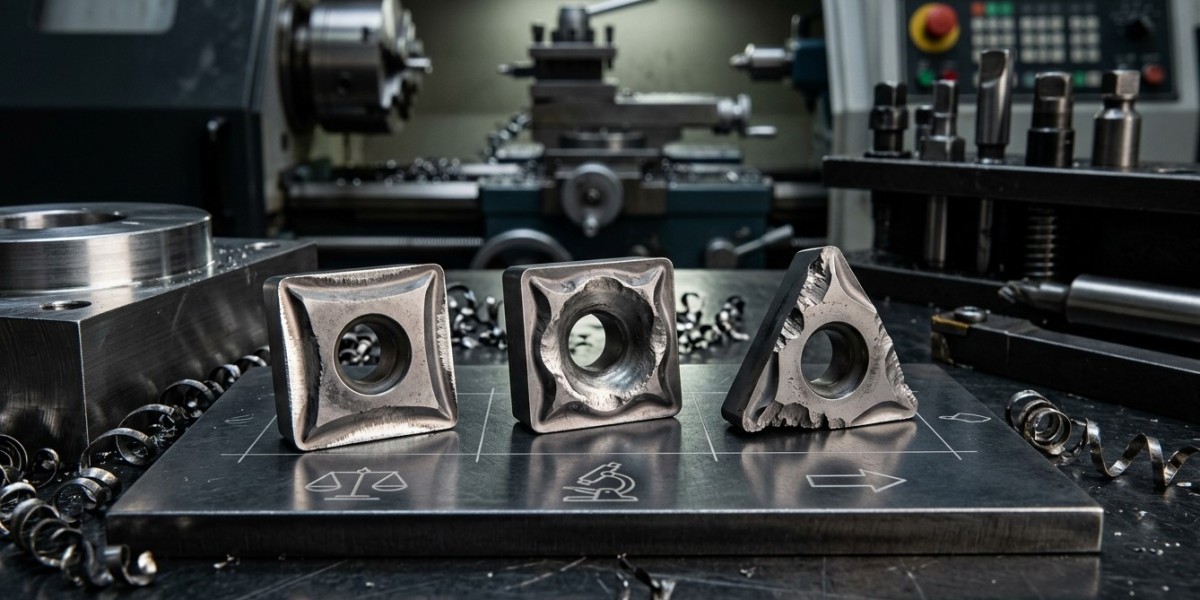

Cutting tools are essential components of modern machining operations. Whether used for turning, milling, drilling, boring, threading, or other CNC processes, their condition has a direct effect on productivity, dimensional accuracy, surface finish, and manufacturing costs. Every cutting tool eventually experiences wear, but the pattern of wear can provide valuable information about what is happening during the machining process.
Understanding cutting tool wear patterns allows operators and production teams to identify problems before they result in tool failure, poor-quality components, or unexpected machine downtime. Different forms of wear can indicate excessive cutting speed, incorrect feed rates, poor tool geometry, vibration, inadequate coolant, improper tool holding, or unsuitable tooling materials.
For manufacturers looking for dependable industrial cutting tools, understanding these wear mechanisms is an important part of improving machining performance. An experienced Industrial Tools Supplier in Dubai can also help businesses select appropriate carbide cutting tools, CNC machining tools, tool holders, and machining accessories for specific applications. Khokhawala Trading LLC provides industrial tooling solutions for CNC machining, manufacturing, engineering, and workshop operations.
What Is Cutting Tool Wear?
Cutting tool wear is the gradual deterioration of a tool's cutting edge during machining. As the tool removes material from a workpiece, heat, friction, mechanical forces, and chemical interactions affect the cutting edge.
Some degree of wear is normal. The objective is not necessarily to eliminate wear completely, but to control it and establish a predictable tool-life cycle.
Uncontrolled wear can eventually cause:
- Dimensional inaccuracies
- Poor surface finish
- Increased cutting forces
- Excessive heat
- Tool breakage
- Machine vibration
- Increased scrap
- Unexpected downtime
- Higher tooling costs
Monitoring wear patterns helps manufacturers understand why a tool is deteriorating and whether the machining process needs adjustment.
Why Understanding Tool Wear Patterns Matters
Simply replacing a worn tool may solve an immediate production problem, but it does not necessarily address the underlying cause.
For example, if several tools show excessive flank wear after a short period, the problem may involve cutting speed, tool grade, workpiece material, or coolant conditions.
Similarly, repeated edge chipping may indicate vibration, interrupted cutting, excessive mechanical shock, or an unsuitable tool geometry.
By identifying the pattern, manufacturers can make targeted improvements rather than repeatedly replacing tools without understanding why they are failing.
Common Types of Cutting Tool Wear
Several common wear mechanisms can appear on CNC machining tools.
1. Flank Wear
Flank wear occurs on the clearance face of the cutting tool where it contacts the machined surface.
It is one of the most common and predictable forms of tool wear.
Moderate flank wear can be part of normal tool life, but excessive flank wear can result in:
- Dimensional changes
- Increased cutting forces
- Poor surface finish
- Increased heat generation
- Reduced machining accuracy
If flank wear develops too quickly, possible causes include excessive cutting speed, unsuitable tool material, abrasive workpiece material, or inadequate tool cooling.
2. Crater Wear
Crater wear develops on the rake face of the cutting tool where chips flow across the tool surface.
It is often associated with high cutting temperatures and chemical interactions between the tool and workpiece.
Crater wear can become more significant at higher cutting speeds and may eventually weaken the cutting edge.
Possible causes include:
- Excessive cutting speed
- High cutting temperature
- Unsuitable tool grade
- Incorrect coating selection
- Poor coolant conditions
3. Edge Chipping
Edge chipping occurs when small pieces of the cutting edge break away.
Unlike gradual wear, chipping can occur relatively quickly.
Common causes include:
- Excessive cutting forces
- Interrupted cuts
- Tool vibration
- Insufficient edge strength
- Incorrect tool geometry
- Poor workholding
- Excessive feed
If repeated chipping occurs, switching to a tougher tool grade or stronger edge preparation may be appropriate, depending on the application.
4. Thermal Cracking
Thermal cracks can occur when a cutting edge experiences repeated heating and cooling cycles.
This can be particularly important in interrupted machining or applications where coolant delivery creates rapid temperature changes.
Thermal cracking may appear as fine cracks running across the cutting edge.
Possible causes include:
- Severe temperature cycling
- Inappropriate coolant application
- Interrupted cutting
- Excessive cutting temperature
- Unsuitable tool material
5. Notching Wear
Notching occurs when wear becomes concentrated at a specific depth-of-cut location along the cutting edge.
It can occur when machining certain abrasive or hardened materials.
Possible contributing factors include:
- Workpiece surface scale
- Abrasive material
- Depth-of-cut concentration
- Chemical wear
- Incorrect cutting parameters
Changing the cutting depth, edge geometry, or tool grade may help reduce this form of wear.
6. Built-Up Edge
Built-up edge occurs when workpiece material adheres to the cutting edge.
It can change the effective geometry of the tool and produce inconsistent machining results.
Built-up edge is often associated with:
- Low or unsuitable cutting speed
- Ductile workpiece materials
- Poor tool surface characteristics
- Insufficient lubrication
- Unsuitable rake geometry
It can lead to poor surface finish and dimensional variation.
What Flank Wear Patterns Indicate
The location and appearance of flank wear can provide useful information.
Uniform Flank Wear
A relatively uniform wear band may indicate normal tool wear under stable machining conditions.
If the wear rate is predictable, manufacturers can use it to establish a practical tool-change interval.
Excessive Flank Wear
Rapid flank wear may indicate:
- Excessive cutting speed
- Abrasive material
- Inadequate tool grade
- Insufficient cooling
- Excessive cutting distance
Reviewing cutting conditions and tool selection may help extend tool life.
Localized Flank Wear
Wear concentrated in a particular area may indicate uneven cutting engagement, workpiece geometry issues, vibration, or depth-of-cut conditions.
What Chipping Patterns Indicate
Repeated edge chipping is usually a sign that the cutting edge is experiencing excessive mechanical stress.
If chipping occurs at the beginning of a cut, possible causes include:
- Incorrect entry conditions
- Excessive feed
- Poor workpiece support
- Tool misalignment
If chipping occurs during interrupted cuts, the tool may require a stronger edge preparation or tougher grade.
If chipping occurs randomly, check tool holding, vibration, machine rigidity, and workholding.
What Built-Up Edge Indicates
Built-up edge is often a sign that the cutting conditions are not well matched to the workpiece material and tool geometry.
It may indicate:
- Cutting speed is unsuitable
- Tool edge is not sufficiently sharp
- Lubrication is inadequate
- Tool geometry is inappropriate
For ductile materials, selecting an appropriate sharp geometry and coating can sometimes reduce material adhesion.
What Excessive Heat Indicates
Heat is a normal part of machining, but excessive heat can accelerate tool wear and affect workpiece quality.
Signs of excessive heat may include:
- Rapid tool wear
- Discoloration
- Edge deformation
- Poor surface finish
- Workpiece dimensional changes
Possible causes include excessive cutting speed, insufficient coolant, poor chip evacuation, excessive tool engagement, or an unsuitable cutting tool.
The Relationship Between Tool Geometry and Wear
Tool geometry has a major influence on how a tool wears.
Important characteristics include:
- Rake angle
- Clearance angle
- Nose radius
- Cutting-edge angle
- Helix angle
- Edge preparation
A sharper edge may reduce cutting forces but can be more vulnerable to chipping under demanding conditions. A stronger edge may tolerate heavier cutting but can generate different cutting forces.
The correct geometry depends on the workpiece material and machining operation.
How Tool Holding Affects Wear
Poor tool holding can create uneven cutting conditions and accelerate tool wear.
Excessive runout can cause one cutting edge to carry more of the cutting load than the others.
This can result in:
- Uneven flank wear
- Edge chipping
- Poor surface finish
- Reduced tool life
- Dimensional variation
Using suitable CNC tool holders and maintaining clean, accurate tool interfaces can help create more consistent cutting conditions.
Tool overhang should also be minimized where practical.
The Role of Cutting Parameters
Cutting parameters are closely connected to tool wear.
Important parameters include:
- Cutting speed
- Feed rate
- Depth of cut
- Radial engagement
- Axial engagement
Excessive cutting speed commonly increases heat and can accelerate wear. Excessive feed may increase mechanical loading and cause edge damage.
On the other hand, overly conservative parameters can reduce productivity and may sometimes create rubbing or unstable cutting behavior.
Tool manufacturer recommendations should be used as the starting point for selecting parameters.
How Coolant Conditions Affect Tool Wear
Coolant can influence temperature, lubrication, and chip evacuation.
However, coolant is not automatically the solution to every tool-wear problem.
Its effectiveness depends on:
- Tool material
- Workpiece material
- Cutting speed
- Machining operation
- Coolant type
- Delivery method
- Concentration and cleanliness
In some interrupted operations, unsuitable coolant application can contribute to thermal shock. Therefore, coolant strategy should be selected according to the specific machining process.
Using Wear Patterns to Improve Tool Life
A structured tool-wear monitoring program can help manufacturers improve production efficiency.
A useful process includes:
- Inspect the cutting edge regularly.
- Record the type and location of wear.
- Measure tool life.
- Compare wear against cutting conditions.
- Check tool holding and runout.
- Review coolant conditions.
- Adjust tooling or parameters.
- Establish a controlled replacement point.
The goal is to replace tools before catastrophic failure while avoiding unnecessary early replacement.
The Role of Precision Measurement
Tool wear often becomes visible through changes in the finished component.
For example, increasing tool wear may result in:
- Larger or smaller dimensions
- Increased taper
- Poor surface finish
- Changes in hole diameter
- Profile errors
Using precision measuring tools such as micrometers, calipers, bore gauges, dial indicators, and other inspection equipment can help identify these changes.
Measurement data can be compared with tool-life information to determine when tooling should be replaced.
Common Mistakes When Managing Tool Wear
Replacing Tools Without Identifying the Cause
If the same wear occurs repeatedly, simply installing another tool may not solve the problem.
Ignoring Tool Runout
Runout can create uneven tool loading and accelerate wear.
Using Incorrect Cutting Parameters
Generic cutting data may not be suitable for every material and tool combination.
Overlooking Machine Rigidity
Vibration and deflection can cause premature edge damage.
Ignoring Tool Geometry
A tool grade alone does not determine performance. Geometry must also match the operation.
Failing to Record Tool Life
Without records, it becomes difficult to identify trends and establish reliable tool-change intervals.
Best Practices for Cutting Tool Wear Management
Manufacturers can improve tool performance by following these practices:
- Select the correct tool material and grade.
- Match tool geometry to the application.
- Use suitable CNC tool holders.
- Minimize runout and tool overhang.
- Follow recommended cutting parameters.
- Maintain appropriate coolant conditions.
- Monitor tool wear regularly.
- Inspect finished components.
- Record tool-life data.
- Replace tools before catastrophic failure.
- Review recurring wear patterns to identify process problems.
These practices help turn tool wear from an unexpected problem into a measurable part of the machining process.
Benefits of Monitoring Cutting Tool Wear
Effective wear monitoring can provide several advantages:
- Longer tool life
- Improved machining accuracy
- Better surface finish
- Reduced tool breakage
- Lower scrap rates
- More predictable production
- Reduced machine downtime
- Better tooling costs
- Improved CNC productivity
- Greater process stability
For high-volume production, even small improvements in tool life can have a meaningful impact on overall manufacturing costs.
Conclusion
Cutting tool wear is an unavoidable part of machining, but its patterns provide valuable information about the health of a machining process. Flank wear, crater wear, edge chipping, thermal cracking, notching, and built-up edge can each indicate different issues involving cutting speed, feed, tool geometry, workpiece material, coolant, vibration, or tool holding.
By monitoring wear patterns rather than simply replacing tools when problems occur, manufacturers can make better decisions about industrial cutting tools, cutting parameters, CNC machining tools, and machining accessories. Reliable CNC tool holders, proper maintenance, and regular inspection with precision measuring tools can further improve machining consistency.
For businesses seeking dependable tooling solutions, Khokhawala Trading LLC is an experienced Industrial Tools Supplier in Dubai, supporting CNC machining, manufacturing, engineering, and industrial workshop applications. A systematic approach to cutting tool wear can help manufacturers extend tool life, reduce unexpected failures, improve component quality, and achieve more efficient production.